
.jpg)
.jpg)
Thank you for choosing an AMS Big bore Kit. The cylinder jugs in your AMS kit have been precision bored, diamond honed, cleaned and quality checked while held in special torque plates, which simulates assembled engine stressed conditions. The enclosed piston rings' end gaps have been properly set during this process as well. Because the jugs change shape when assembled on the engine, or held in torque plates, the cylinder bore and ring end gaps cannot be accurately measured or set with the jug in a "free" state. Should you have any questions or concerns about your cylinders, pistons or rings, please do not hesitate to call us. 817-335-9331
1. Prior to installing, be sure to wash and rinse your intake manifold, air cleaner backing plate, and if, applicable, air filter element. After washing them, place them in a plastic trash bag to keep them clean until time for assembly. Piston & cylinder contamination damage is often caused by dirt/carbon/debris hiding inside the intake manifold, and/or air cleaner/filter element.
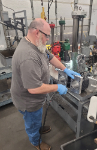
2. Make sure your hands, tools, bench top, and work area are clean - not just wiped off, but washed clean. Discard all soiled or used shop towels (these are another major source of contamination). Have a supply of clean shop towels or paper towels handy.
3. The cylinder jugs & pistons have been cleaned, however they should be inspected and if necessary wash them, immediately prior to assembly, in hot soapy water and rinse in hot water; dry with paper towels, then apply clean motor oil to the cylinder wall. Do NOT use solvents, carb cleaner, or brake cleaner. We strongly suggest washing them if they have been opened and exposed to a shop or garage environment for even a short while, as its likely dust and airborne grit has settled on them.
4. Grasp each end of the Spirol Lock pin circlips and stretch them out, approx ½" to ¾" length, like stretching a coil spring. See pics at http://www.uempistons.com/installation_instructions/kb_installation.pdf
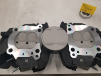
5. Orient the piston so the larger valve relief pocket in top of piston faces toward the fore/aft center of engine's "V", which is the intake side of each jug/head (this will be put the larger valve pocket to the rear on the front piston, and to the front on the rear piston). Some pistons will also be stamped "INTAKE" - to identify the larger valve pocket, again this faces toward the engine's "V" center. Install a Spirol Lock in the circlip groove on the left* side of each piston, after orienting. (* Left / right when sitting on the motorcycle.) To install the Spirol Lock, start one end in the groove, then use a small screwdriver to push the each progressive coil into the groove, working in a circular pattern around the pin bore. Make sure all the coils and ends are completely seated in the groove. If not seated completely the clip can unwind under load and cause severe engine damage.
6. 105" kits: skip to step #7 96" kits only: We have made a running packaging change to our kits: supplying them with the lower oil ring support spacer pre-installed.* Locate the dimple in this spacer, and verify its protrusion is facing down, away from the piston's crown AND that it is located over the notch created by the wrist pin bore. The spacer's end gap will be 90° to the pin. Slide the spacer all the way up in the groove, to allow clearance for the pin to pass thru. * (If the support spacer ring has not been prefit, spiral it onto/into the oil ring groove, with the dimple oriented as noted above. Additional info can be found here or call AMS at 817-335-9331 for tech help).
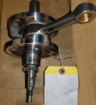
7. Make sure the pistons, wrist pins, and connecting rods are exposed to the same shop temperature for the same amount of time, as a temp difference can effect size and fit during assembly. Do not handle the wrist pins excessively as the warmth from your hands can also them to expand and make assembly difficult. Make sure the connecting rod bushings are clean and properly sized. Coat the rear connecting rod bushing liberally with clean oil - to prevent contamination, we prefer to soak oil onto a clean paper towel and carefully wipe the oil onto the parts.
8. Refer to your factory manual's section on installing pistons onto connecting rods. Use rubber hose over studs as noted in the manual to protect piston skirts from being damaged. Oil the rear piston's pin bore, and wrist pin. Again, work cleanly. Carefully start the pin into piston's pin bore. Take care to start it straight, without cocking it, to prevent burring the pin bore. Orient the rear piston with the larger valve pocket facing forward, over the connecting rod. Install the pin. If the pin, piston bore, and oil are clean, and temp stable, the pin can be pushed in with your thumb, smoothly, yet firmly (like a "hydraulic fit") until it seats gently against the previously installed Spirol Lock. Do NOT hammer on the pin. If you encounter excess resistance, stop, remove the pin, clean everything again, re-oil the parts, and carefully start the pin again. If you continue to have trouble, please call AMS at 817-335-9331 for assistance.
9. Verify the rear piston's orientation (larger valve pocket / "INTAKE" faces forward). Install the remaining Spirol Lock, as described in steps 4 & 5. Take care it is completely and fully seated in the piston's groove. Next, verify the piston can easily rotate about the pin, and float side to side.
10. Referring to your factory service manual, fit the piston support plate, HD Tool # 42322, to hold the piston steady while installing rings. If you do not have a support plate, one can be easily fashioned from hardwood. (Some techs use two 6" long wooden dowel rods. As long as the piston doesn't flop around, or get scratched or dented, use whatever works :. )
11. Next slide the oil ring support spacer all the way down in the oil ring groove. Verify dimple is protruding down, and located over / aligned with one of the wrist pin. Rotate spacer if needed to align.
12. Using the rear piston's ring pack, fit the 3 piece oil control ring as follows:
With any side up, carefully spread wavy expander just enough to slip it over piston and into lower groove, so it is sitting atop the support spacer. Position the ends of expander so they are also over/aligned with the wrist pin bore (does not matter which end of pin). Check that expander's ends are butting squarely, and not over-lapping.
Next, at about 1" on either side of side of the expander's ends, start one end of a thin rail spacer into the lower gap left between the wavy expander and support spacer. It does not matter which side of rail faces up. Spiral the rail into place. Make sure it sits in the groove all way round.
Next start the other rail spacer 1" in the opposite direction from expander's ends; so the rail ends are staggered left and right of the expander's ends. Spiral the rail into the gap between the expander and the top of the ring groove. Check that it sits in groove all way round, and that this 3 piece oil ring assembly can easily turn / float in piston groove.
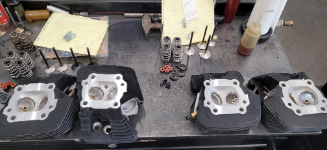
13. Identify the second, oil scraper ring: it has dull black face and sides. Fit as follows:
Determine top side of second ring by locating a small "dot" drilled into one of ring's flat side surfaces; the dot is located about ½" from the end gap. An easy way to find the dot is to firmly rub your thumb across side surfaces of the ring, near end gap. This slightly polishes the black oxide and leaves the darker dot easier to see. When ring is installed, dot must face up. Using a ring expander tool or your thumbs, gently spread ring just enough to slide it down over piston and into 2nd (middle) ring groove, If you use your thumbs, wrapping them with duct tape helps protect against the ring's sharp edges. Do not over spread ring or it will break. Do not spiral it on as this can permanently distort the ring and cause oil consumption / blow-by problems. Verify dot is facing up, and that ring is free to rotate move in groove. Rotate it so the end gaps are "clocked" around the piston toward the left rear.
14. Identify the top compression ring: it has a shiny gray face with dull dark gray or black sides. It does not have a dot on the side. It can be installed with either side facing up. Carefully spread it, just enough to slip it squarely over the piston and into the top groove. Do not spiral it on. Verify it can rotate / move freely in its groove. Clock it around the piston so its end gaps are located toward the right rear. This staggers all the rings' end gaps so they are not aligned.
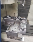
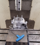
15. With the jug thoroughly cleaned, and cylinder wall oiled, place the base o-rings in position and install the jug as noted in the factory service manual. Be sure to clean your hands and tools, especially the ring compressor band prior to installing each jug. Also oil the inside surface of the ring compressor band, as this will aid ring installation and help reduce the risk of breakage. Use extreme care that none of the piston rings "pop out" from under the ring compressor band while squeezing it to compress the rings; also watch closely that none of the rings pop-out as they transition from under the compressor band and into the cylinder - otherwise the rings can be easily broken - or worse, in the case of an oil control ring, folded over - without you ever noticing the problem until after the engine is assembled and run for several miles. Ring "pop-out" is the number one assembly error, and usually causes severe piston/ring/jug damage.
16. Refer to your factory service manual, and repeat the above steps as needed to install the front piston/jug.
If you have any questions or concerns about your AMS Big Bore Kit, please call us at 817-335-9331. Tech help is free and we're always glad to help!
If you need help after normal business hours, or on the weekend please call 817-266-9870 or 817-266-9873.
Find us on Facebook at www.facebook.com/AMS.machine
Automotive Machine & Supply,Inc © 2012, 2013, 2014, 2015, 2016, 2017